Researchers
Ronald Faller
Robert W. Bielenberg
John Reid
Dylan Meyer
About the research
Portable concrete barrier (PCB) systems are often used to redirect errant vehicles through a combination of inertial resistance, lateral friction loads, and tensile loads developed from the mass and friction of the barrier segments. State departments of transportation (DOTs) and other end users may wish to utilize minimal length PCB installations to shield a hazard or work zone or limit the number of barriers required on the upstream and downstream ends to reduce overall system length. However, concerns with the performance of shorter PCB installations include increased lateral deflections and working widths and barrier pocketing. Additionally, no impact testing has been performed near the upstream or downstream ends of the free-standing PCB system to determine the limits of the length of need (LON) of the system. These impacts may increase the potential for gating through the system, pocketing, rapid deceleration, and/or vehicle instability. The objective of this research study was to investigate and evaluate the safety performance of a previously developed F-shape PCB system to determine minimum system length and the number of barriers required for the beginning and end of the LON. LS-DYNA simulation modeling was applied to determine potential beginning and end of LON points on reduced system lengths to select a configuration for full-scale testing and evaluation of a minimum length PCB system. A 100-ft long PCB installation was selected, and full-scale crash testing was conducted on the beginning and end of LON of the reduced length system. Test no. NELON-1 was conducted to MASH test designation 3-35 criteria on the beginning of LON of the 100-ft long PCB installation, and the vehicle was safely redirected. Test no. NELON-2 was conducted to modified MASH test designation no. 3-37 criteria on the end of LON of the 100-ft long PCB installation, but the test was deemed a failure as the vehicle demonstrated a roll angle in excess of 75 degrees. Review of the crash test results suggested that a nine barrier or 112.5-ft long PCB installation would perform acceptably.
Project Details
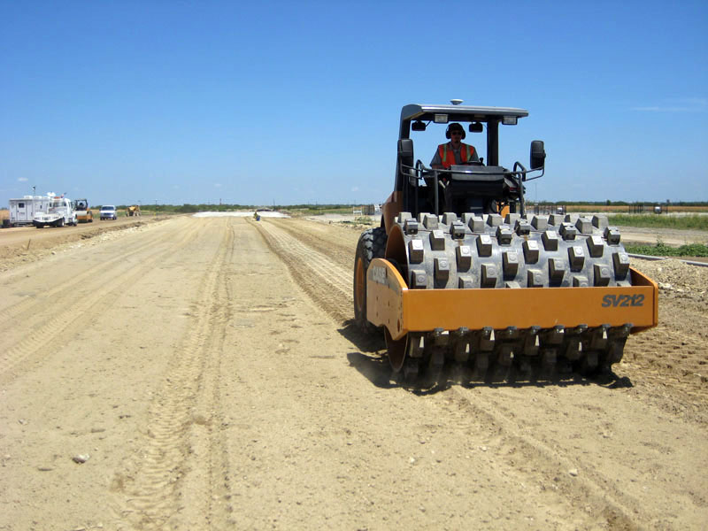
Ammann Construction Equipment
Bomag Americas, Inc.
Case Construction Equipment
Dynapac
Federal Highway Administration Transportation Pooled Fund (TPF-5(128))
Sakai Heavy Industries Ltd.
State DOT Partners: IN, KS, MN, MS, ND, NY, TX
Transtec Group
Researchers
David White
Heath Gieselman
Pavana Vennapusa
About the research
A full description of the project is available on the Federal Highway Administration pooled fund study website.
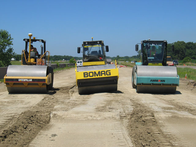
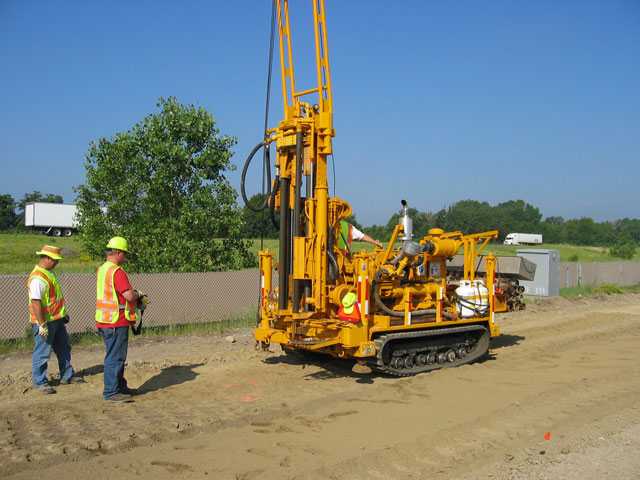
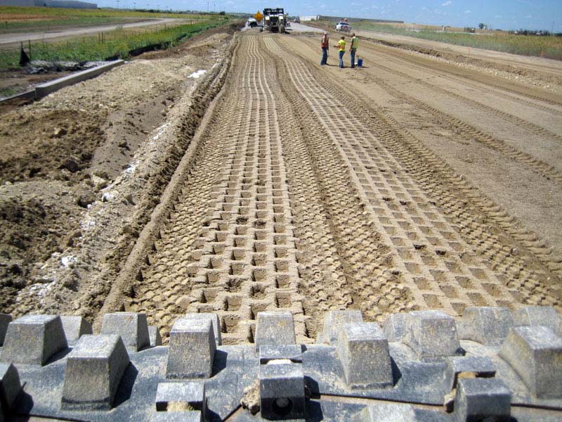
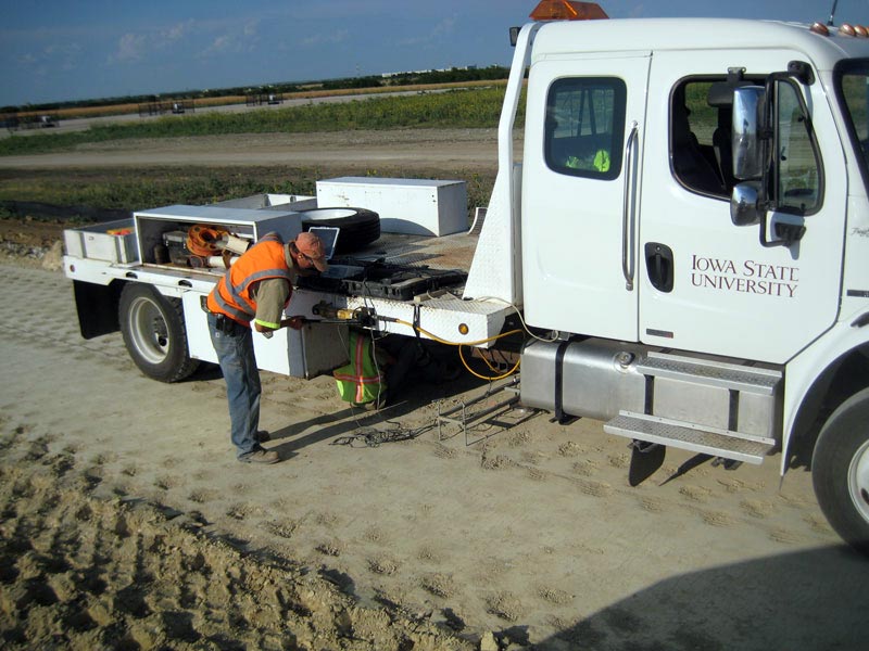
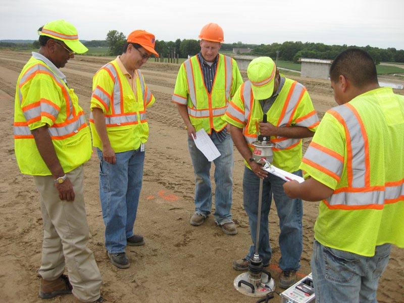
CEER team members are involved in the project to provide expertise with compaction monitoring technologies, conduct in-situ testing on field project sites using the Geotechnical Mobile Lab and open houses on field project sites to disseminate project findings, and provide training to agency and industry participants.
Project Details
07/01/06
10/31/10
Ammann Construction Equipment
Bomag Americas, Inc.
Case Construction Equipment
Caterpillar
Dynapac
National Cooperative Highway Research Program 21-09
Sakai Heavy Industries Ltd.
State DOT Partners: MN, NC, FL, MD, CO
Transportation Research Board
Trimble Navigation
Researchers
Michael Mooney
David White
Robert Rinehart
Normal Facas
Mark Thompson
Pavana Vennapusa
Odon Musimbi
About the research
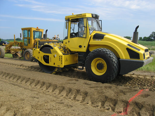
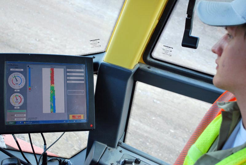
The NCHRP Project 21-09, “Intelligent Soil Compaction Systems,” was undertaken to investigate intelligent soil compaction (IC) systems and to develop generic specifications for the application of IC in quality assurance (QA) of soil and aggregate base material compaction. The term intelligent soil compaction systems was defined to include (1) continuous assessment of mechanistic soil properties (e.g., stiffness, modulus) through roller vibration monitoring; (2) automatic feedback control of vibration amplitude and frequency; and (3) an integrated global positioning system to provide a complete geographic information system-based record of the earthwork site. An equally important term is roller-integrated continuous compaction control—defined by IC components (1) and (3).
Roller-integrated continuous compaction control (CCC) technology was initiated in Europe in the 1970s and has been used in European practice for nearly 20 years. The first European specification for roller integrated CCC was developed in Austria in 1990. Today, four European countries have soil compaction QA specifications using roller-integrated CCC (Austria, Germany, Sweden, and Switzerland) and U.S. states are beginning to implement pilot specifications (e.g., Minnesota). In European specifications the use of automatic feedback control IC rollers is permitted during compaction but not during QA because the roller measurement values (MVs) can be strongly influenced by varying amplitude and frequency. The dependence of roller MVs on frequency and amplitude in particular was verified in this study and further determined to be quite complex and difficult to predict. Accordingly, the recommended specifications developed here allow IC during compaction but do not permit the use of automatic feedback control IC during roller-based QA.
The following are the key items covered in this project:
- Recommended Specifications for Roller Integrated CCC in Earthwork QA
- Fundamentals of Roller Measurement Systems
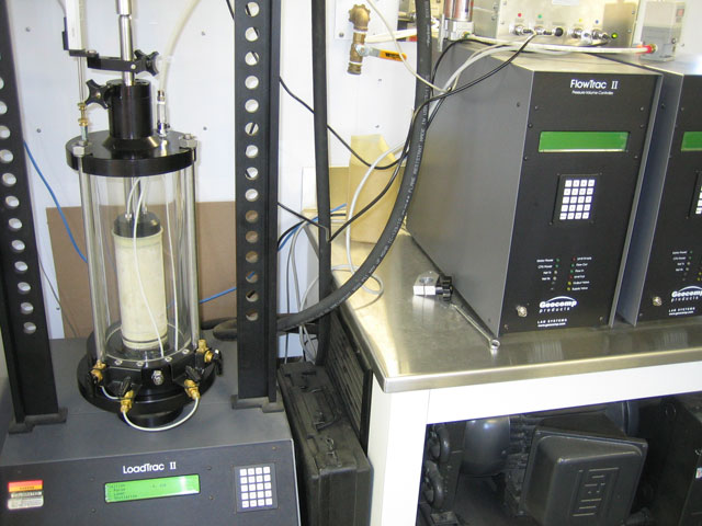
- Relationship Between Roller-Measured Stiffness and In Situ Stress-Strain-Modulus Behavior
- Evaluation of Automatic Feedback Control-Based Intelligent Compaction
- Correlation of Roller Measurement Values to Spot-Test Measurements
- Case Study Implementations of Recommended Specifications