InTrans / May 01, 2015
Accelerated bridge construction: Constructability is KEY!
Go! Magazine
posted on May 1, 2015
This article is the fourth in a series: The ABCs of putting “drivers first” in bridge projects (ABC=accelerated bridge construction)
More than 100 years ago, Ransom Olds and Henry Ford revolutionized manufacturing processes when they developed the assembly line for constructing automobiles faster. The concept was straightforward: First, manufacture (prefabricate) all the necessary parts. Then, assemble the parts in a linear, progressive fashion. With the assembly line, the production of Ford automobiles jumped from 10-20 vehicles a day to more than 200 vehicles a day! Now, that is accelerated car construction.
For an assembly line to work:
All the individual parts must fit together perfectly.
Installation errors must be minimized.
Construction schedules for each section must be perfectly timed.
Whether for automobiles or bridges, these three characteristics define “constructability.” Constructability is the key to successful accelerated construction of a high quality end product.
Challenge: “constructable” integral bridge abutments for ABC
Like automobile assembly lines, accelerated bridge construction (ABC) typically relies on prefabricated parts. The parts are manufactured offsite and then quickly assembled at the bridge location. But it can be a real challenge to prefabricate bridge parts that fit together perfectly, with minimum installation errors.
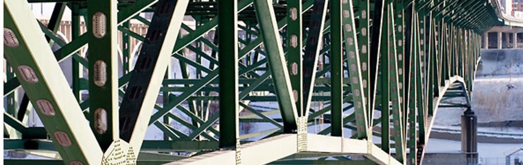
One example is couplers for integral abutments. The abutments (foundations) of a bridge are those sections that support the bridge beams and transfer the weight of traffic loads from the bridge to the ground. Integral abutments are physically locked to the bridge superstructure, as shown in Figure 1 (as opposed to stub abutments on which bridge beams simply rest, with limited connections, as shown in Figure 2).
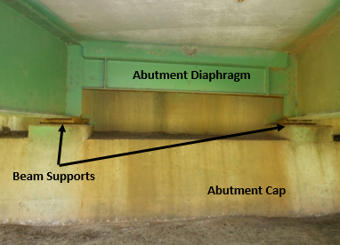
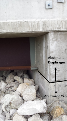
Integral abutments improve the service life of the structure and reduce the initial cost of the bridge. When a bridge is built using traditional construction methods (often called cast-in-place, or CIP, construction), steel bars (rebar) are left sticking out of the top of the abutment top, or cap, when the abutment cap is poured. Then when the connecting section of the abutment, or diaphragm, is cast on top of the cap and rebar, the concrete also surrounds the ends of the girders, locking the cap and the diaphragm and the girders together. See Figures 3 and 4.
But with ABC, constructing an abutment from prefabricated sections that behaves like an integral abutment gets complicated.
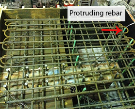
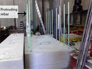
protruding steel rebar from abutment cap (ready to cast)
Prefabricated caps that have protruding rebar are difficult to move and transport. Plus, if the rebar is bent or located even half an inch off, it will not align with the corresponding couplers in the prefabricated diaphragms.
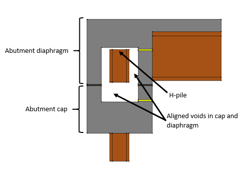
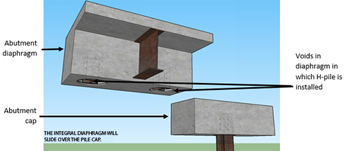
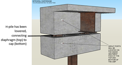
To solve this problem, researchers at Iowa State University have developed a new kind of coupler: pile couplers. With pile couplers, a large cylindrical void is cast into both the prefabricated abutment cap and the prefabricated abutment diaphragm. Inside the void in the diaphragm is a short length of steel H-pile (so named because of its shape). The H-pile fits all the way into the void; that is, there is no protruding steel. To connect the sections, the diaphragm is set on top of the cap, and the two voids in the two sections are aligned. Then the the H-pile is manually lowered with a cable so that half of the H-pile is in the bottom void and the other half is in the top void. Finally, the entire void surrounding the pile section is filled with grout or concrete to lock the sections together and create the integral abutment connection. Figures 5-7 illustrate the concept of the pile coupler connection.
The pile coupler detail improves the constructability of the connection. The cap and diaphragm fit together with some tolerance for slight differences in the location of the voids. In addition, relatively fewer couplers are required than with other coupler types, and pile couplers require no specialized equipment or hardware.
Related links
This article is the fourth in a series about a variety of innovative ABC advancements being implemented across the country. See the previous articles:
“The ABCs of putting drivers first in bridge projects”
“The many faces of bridge engineering”
“Build bridges faster—but can you keep them together?”
Check out the ABC-UTC homepage: http://www.abc-utc.fiu.edu/
See the Federal Highway Administration initiative to promote ABC (scroll to bottom of page for videos, photos, and more): http://www.fhwa.dot.gov/everydaycounts/edctwo/2012/abc.cfm
By Travis Hosteng, Bridge Engineering Center, Iowa State University